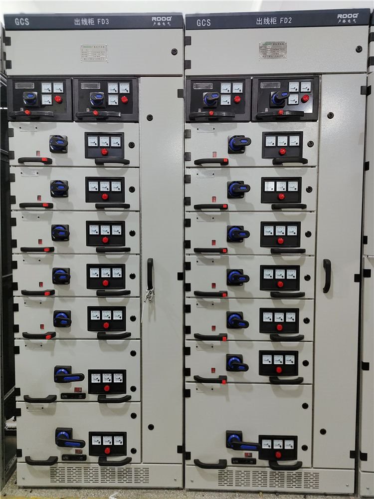
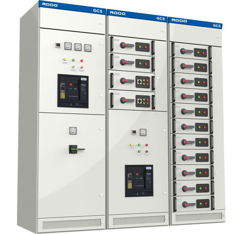
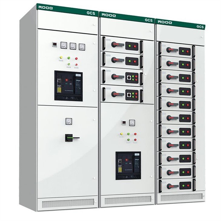
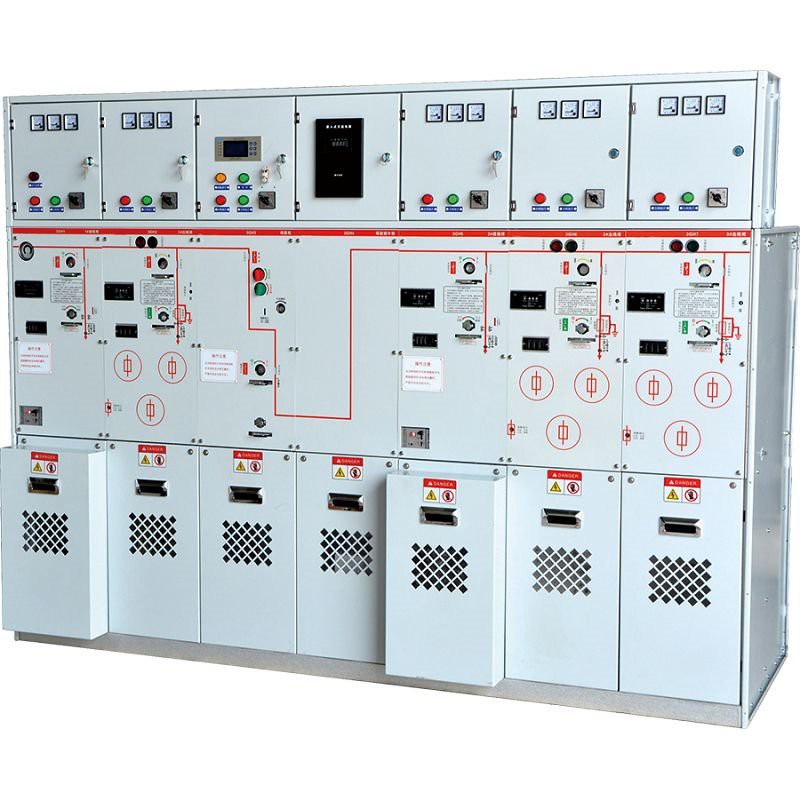
GCS Withdrawable Switchgear
Outline
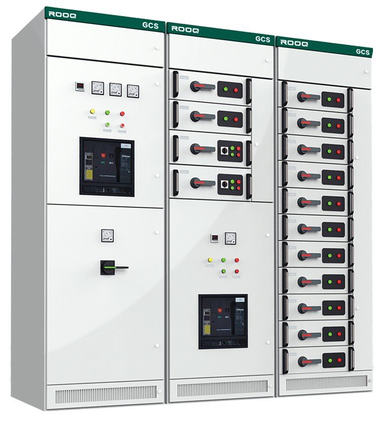
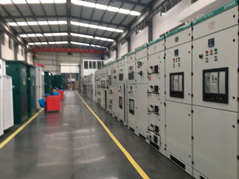
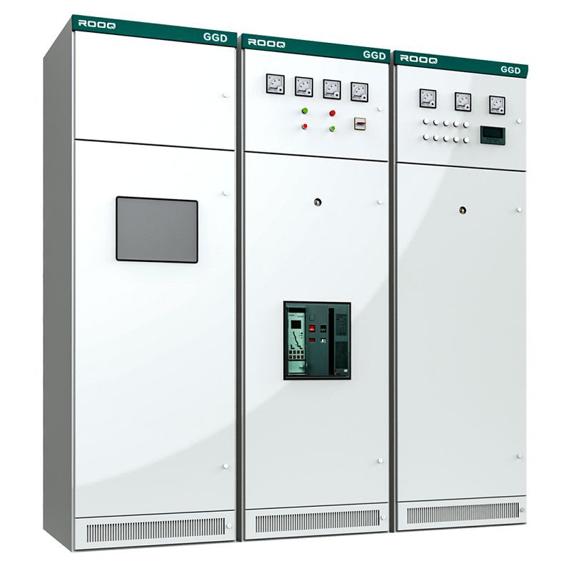
GCS withdrawable switchgear is suitable for power conversion, distribution and control in low-voltage distribution system of power, power distribution, motor control center, capacitance compensation, etc. Such as power plants, substations, petrochemical, factories and mining enterprises, hotels and high-rise buildings and other low-voltage distribution systems
Executive standard
IEC 60439-1 Low voltage switchgear and control-gear assemblies
Part 1:Type test and partial type test assemblies
GB 7251.1 Low voltage switchgear and controlgear assemblies
Part 1: type test and partial type test assemblies
JB/T 9661-1999 Low voltage withdrawable switchgear and other standards
Service Environment
● The ambient air temperature shall not exceed + 40 ℃, and the average temperature within 24h shall not exceed + 35 ℃.
● The lower limit of ambient air temperature is - 5 ℃.
● For indoor installation and use, the altitude of the place of use shall not exceed 2000m.
● The air shall be clean. When the maximum temperature is + 40 ℃, the relative humidity shall not exceed 50%; Higher relative humidity is allowed at lower temperatures. For example, the relative humidity is 90% at + 20 ℃, but considering the change of temperature, moderate condensation may occur occasionally.
● During installation, the inclination with the vertical plane shall not exceed 5 °.
● The device is suitable for the transportation and storage process of the following temperatures: - 25 ℃ - + 55 ℃, up to 70 ℃ in a short time (no more than 24h). Under these limit temperatures, the device shall not suffer any irreparable damage, and shall be able to work normally under normal conditions.
● The device shall be installed where there is no violent vibration and impact, and where the electrical components are not enough to be corroded.
● If the above service conditions cannot be met, the user shall negotiate with the company.
Specification
1. Basic Technical parameter
ITEM | Technical Data | |
Rated insulation voltage Ui | AC 660(1000)V | |
Rated working voltage Ue | Main Circuit | AC 380(660)V |
Auxiliary circuit | AC 380V/220V/24V | |
Rated Frequency | 50-60Hz | |
Rated Current | Horizontal bus-bar | ≤4000A |
Vertical bus-bar | 1000A | |
Rated short-time (1s)withstand current lcw | 50(80) kA | |
Rated peak withstand current lpk | 105(176)kA | |
Protection Level | IP 40 , upto IP54 | |
a) Main circuit scheme of switchgear
There are 32 groups and 118 specifications in total, and the rated working current is 4000A, which is suitable for distribution transformers of 2500kVA and below.
b) Auxiliary circuit scheme of switchgear
There are 120 auxiliary circuit schemes of switchgear
c) Bus-bar
All busbars adopt TMY - T2 series hard copper bar.
i.Horizontal bus is placed in the rear of the cabinet bus compartment, 3150A and above for the upper and lower double layer layout, 2500A and below for the single layer layout.
Horizontal busbar in switchgear
Item | Rated Current(A) | Specification (mm) |
1 | 630 | 50*5 |
2 | 1250 | 60*10 |
3 | 1600 | 80*10 |
4 | 2000 | 100*10 |
5 | 2500 | 2*(80*10) |
6 | 3150 | 2*(100*10) |
7 | 4000 | 3*(100×10) |
ii. The vertical bus adopts high-quality hard copper tinned bus 40*6/60*6/100*6
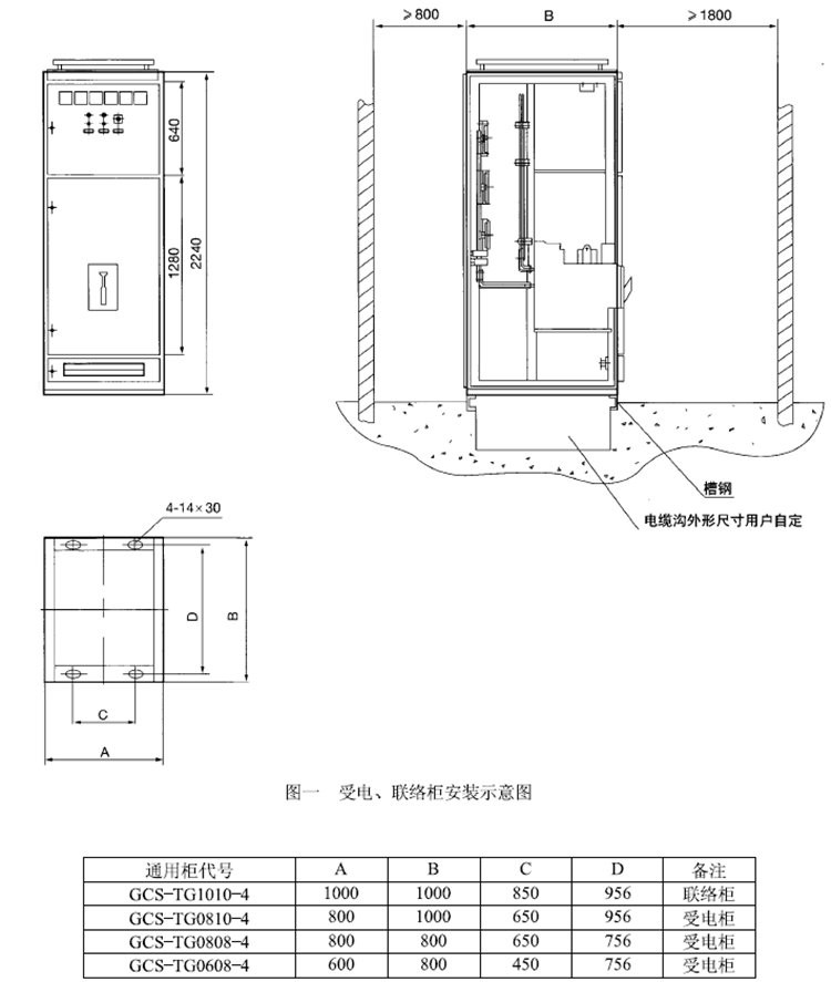
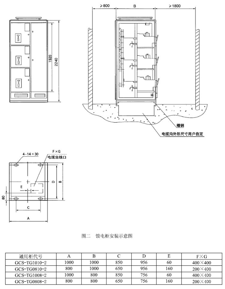
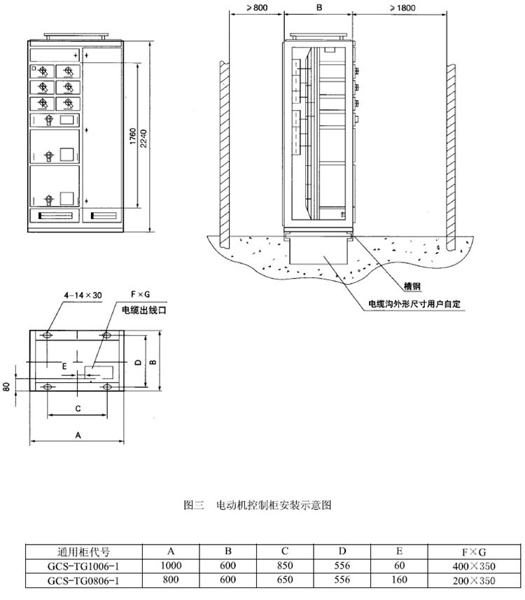
Measurement
Item | (H) mm | (W) mm | (D) mm |
1 | 2200 | 400 | 800 |
2 | 1000 | 600 | 800 |
3 | 1000 | 800 | 600 |
4 | 800 | 1000 | 1000 |
5 | 600 | 800 | 1000 |
